Products
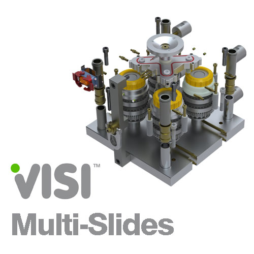
VISI Multi-slides is an extension of VISI Progress. It has been developed for the design of CAMS used in “multi slide machines”, specifically for the bending process.
VISI Multi-slides is an extension of VISI Progress. It has been developed for the design of CAMS used in “multi slide machines”, specifically for the bending process. Quickly and efficiently it allows the simulation and synchronisation of the bending cycle performed in succession to the cutting action of the progressive tool. Construction of the CAM form and all relevant dimensions is automatic for each specified type of machine.
Features at a glance:
Multi-slide machine database
Slides library, customisable transmission ratio
Kinematic simulation
Interference checking against the fingers / flanges
Sharing of the un-used angular section to optimize the finger movement
Cycle diagram
Automatic cam construction
Progressive die tooling is a popular process for producing sheet metal parts although it is not the only technology in this field. The fundamental concept of “one tool produces all” is not always an advantage and in some cases a “transfer” process provides a better solution (automotive, body, chassis, etc). However, a combination of these two technologies can provide an extra advantage, especially when the part production needs the application of specific technologies (welding, assembling, etc). Multi-Slides is an example of this combination: the progressive die tool remains in control of the cutting and drawing actions, whilst the bending cycle is performed by this special multi-slide tooling.
Synchronised and Optimised. Starting from the unfolding steps, every finger can be designed by using a series of quick 2D sketches. These sketches are used to obtain the number of movements, stroke value and the orientation of each finger. This information is then used as input data to compile a “computation table”.
On completion of the computation table, a kinematic simulation of the entire cycle can be performed. This enables the designer to check the available synchronisation level, possible interferences among moving parts, and the optimisation level by checking the value of the unused angular sector.


